Upload Geometry
Introduction
After creating a brand new case in ColdStream, you will need to upload the geometrical entities. This article delves deeper into how you can upload your CAD model to the platform. This article assumes that necessary preparations have been completed. For more information about how to prepare your geometry, click here.
CAD file format
Uploading your geometry happens via CAD files in the STEP file format. The STEP files are limited to the following specifications:
- Application Protocol (AP) 214: intended for the automotive mechanical design process. This is mostly the standard export of your CAD software, but it can be checked and changed in the export options.
- The STEP file is a Part STEP file, it is not an Assembly STEP file. The difference should be marked in your CAD software. If you do have an assembly, export each part separately or contact our support staff.
Uploading your geometry
There are two methods to populate your case with all relevant regions, subregions, and boundaries.
Method 1
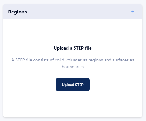
The first method is to upload one STEP file which contains all relevant regions, subregions, and boundaries. This method can be used as the initial upload of your geometry. After clicking on "upload STEP", select your step file to upload and click on "populate case". The uploading process that now has been initiated involves the following steps:
- The contents of your file will be disassembled, meaning that for each body a (sub)region will be created, and that surfaces will be assigned as boundaries to regions.
- The geometry will be checked. Bodies and surfaces that do not satisfy these checks (see geometry guidelines) will be given an error on and will not be created.
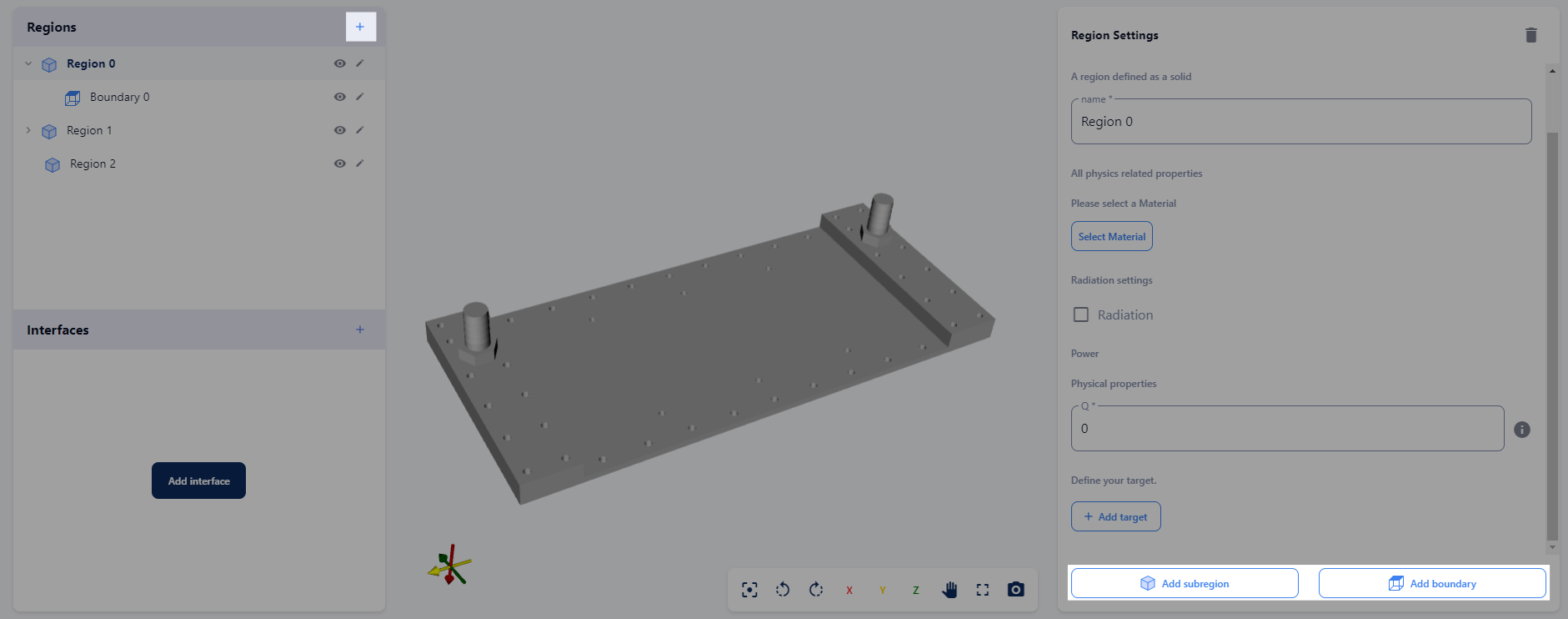
Method one: upload one STEP file containing all regions, subregions, and boundaries.
Method 2
In the second method, you upload each region, subregion, and boundary as a separate STEP file. A new region can be uploaded by clicking on the "plus" sign next to regions. After selecting the relevant region type, the buttons to upload boundaries and subregions will appear in the region settings window.
Method two: Upload regions, subregions, and boundaries as separate STEP files.
ImportantThese are some of the checks that are performed on the geometries:
- Make sure all regions are well connected.
- Check for any unassigned boundaries; make sure all boundaries are touching their parent regions.
- Partial intersection of entities; geometries that are partially intersecting each other can cause meshing issues.
- Check for any wires or points that might have accidentally ended up in the STEP file while exporting from your CAD software.
Naming
On initial CAD upload, the naming of the geometries is handled automatically. The names of regions and subregions are read from the STEP file and assigned to respective entities.
Due to differences in geometry definition between different CAD software, names from some STEP files will not be read. In this case, a default naming format will be used: type number. Where 'type' can be either region, subregion, or boundary. The numbering starts with 0. Within each region, the numbering is reset to 0 for subregions and boundaries.
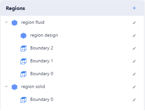
Naming convention if boundary names cannot be read from the STEP file
Geometry guidelines
In general, the platform requires input that finds a good balance in the level of detail that is present in the geometry input. Insufficient detail limits the predictive value of simulations, whereas too much detail can hamper separating the important from the non-important.
Here are some guidelines for the level of detail:
- Take care of small features: small features will be captured as well as possible by a simulation, but the more small features, the harder the balance between capturing all of them and capturing the global picture. Leave small features only when they matter.
- Avoid “idealistic” or non-manufacturable” geometry, such as sliver surfaces, cusps, knife-edges, and similar degeneracies.
- Avoid excess realism in the form of geometric details such as embossed or engraved text, fasteners, or separate screws.
- When having very thin surfaces or regions, consider simply removing them or replacing them with a thermal interface.
- Make sure to give distinct names to regions, subregions, and boundaries.
The geometry is preferably oriented according to XYZ-axes. This will improve the quality of the simulation.
Updated 8 months ago