Regions, subregions and boundaries
Introduction
| Region | Subregion | Boundary | |
|---|---|---|---|
| Geometry type | Volume | Volume | Surface |
| Required | At least one | - Simulation case: No | No |
| - Design case: at least one design subregion | |||
| Part of | NA | One region | One region |
Every case setup starts with uploading the geometry of your case. Usually, a case consists of multiple entities. As an example consider a simple water-cooled heat sink. This heat sink consists of an aluminum base in which cooling channels should be placed and a plastic top plate to seal the heat sink. A heat-generating component is applied at the surface of the aluminum plate. If you want to start a design run for this heat sink, you need to somehow indicate on the geometry the different materials, the fluid type, the location of the inlet and outlet, the location of the heat sources, and last but not least the domain in which cooling channels are allowed to be placed. That’s where the concept of regions, subregions, and boundaries comes into play.
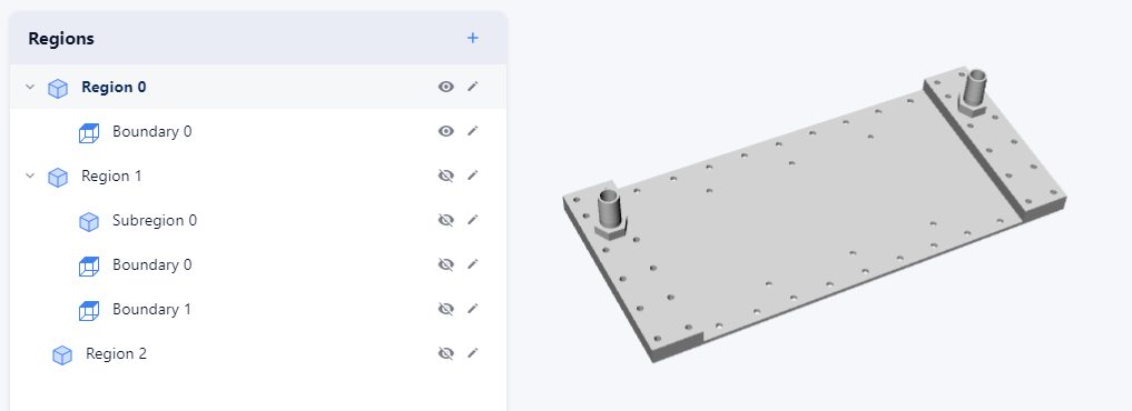
You can upload the parts of your geometry as one of the three entity types: (1) region, (2) subregion, and (3) boundary. Each entity type is explained below.
Region
A region represents the parts of the geometry which consist of the same material. It should always be a closed manifold or consist of multiple closed manifolds. A region can be one of the following two types: a fluid or a solid. If the region is a solid type, it does not have to be one lump but can consist of multiple lumps from the same material. If the region is a fluid type, it does need to be one lump. Every case needs to have at least one region. If a case consists of multiple regions, they should be connected in such a way that all regions together form one lump.
NoteNote that not every part of the same material should be included in the same region. If there are two parts from the same material touching each other but having a thermal interface in between, they should be taken into account as two separate regions to be able to define the thermal interface.
Geometry guidelines
- When having multiple Regions, they have to be connected to interact. This also means that gaps between regions have to be filled, otherwise they will be thermally insulated from each other.
- Regions cannot overlap with each other. Otherwise, it is unclear to which region that part of the domain belongs.
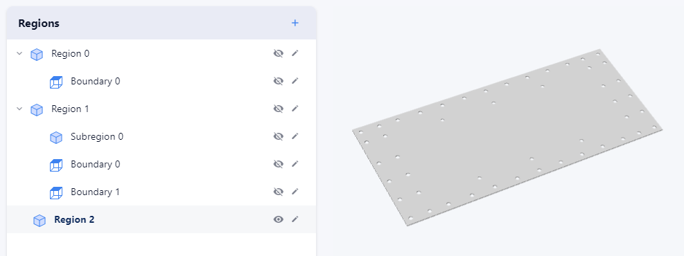
In the example described above three different regions can be distinguished: (1) an aluminum region of type solid, (2) a plastic region of type solid, (3) and a water region of type fluid.
The aluminum region of type solid.
The plastic region of type solid.
The water region of type fluid.
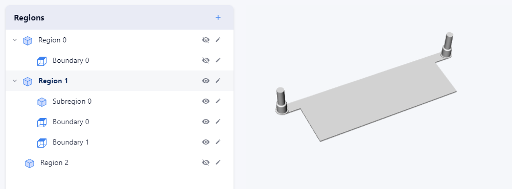
Subregion
Just like a region, a subregion should always be a closed manifold or consist of multiple closed manifolds. The only difference is that a subregion belongs to a region and must always fall entirely within that region. A subregion can be one of the following two types: general or design. A general subregion can be introduced to indicate special conditions in a particular part of a region. If for example, a part of the volume of a region is generating heat, the geometry of that part should be uploaded as a subregion. A design subregion is used to indicate the design region. For design cases, at least one design subregion is required.
Geometry guidelines
- A subregion is a part of a region. It is fully comprised, but smaller than the region it belongs to.
- A subregion cannot be bigger than one region.
In the example described in the introduction one subregion should be introduced: the design region which should fall entirely within the water region.
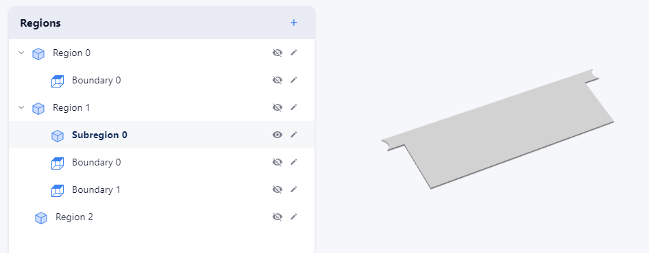
The design subregion which falls entirely within the water region
Boundary
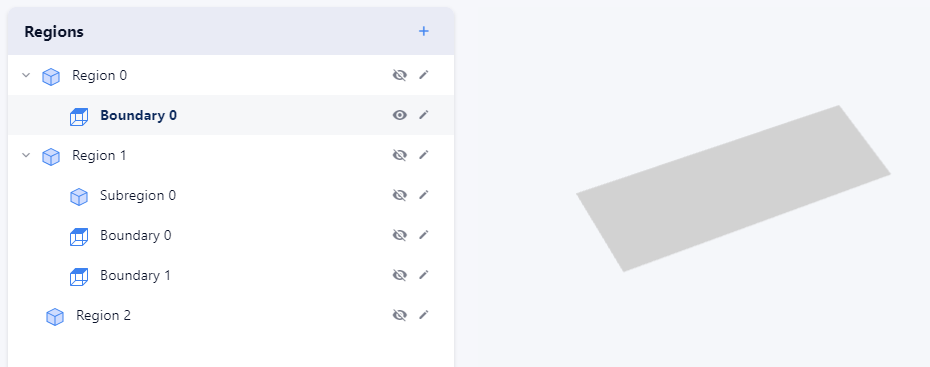
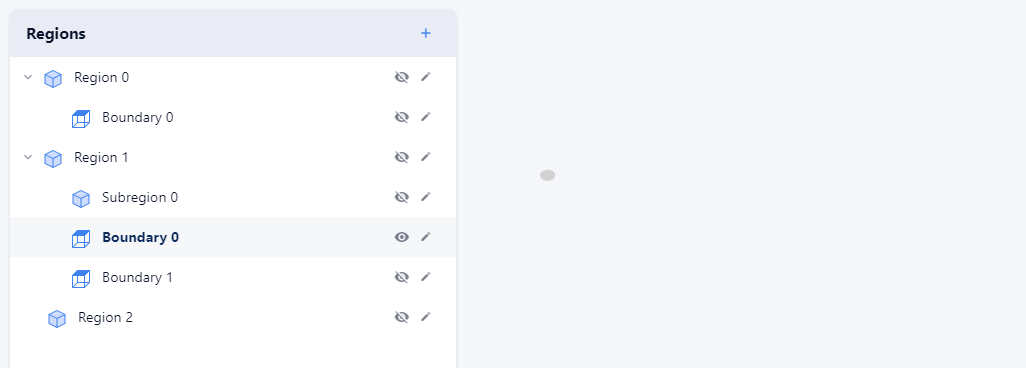
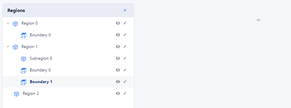
As the name implies, boundaries are used to apply boundary conditions. A boundary is represented by a surface which can be open but can be closed as well. A boundary can consist of multiple non-connected surfaces. One boundary should always be part of the shell of one and only one region.
NoteA boundary with an adiabatic boundary condition is the only one that does not have to be uploaded but is automatically taken into account.
Geometry guidelines
- Boundaries are always a part of the shell of a region, i.e. they are “on” the region and not defined inside the volume itself.
- They should only touch 1 region and not overlap with other boundaries. Thus, they cannot be defined on interfaces between regions.
- Inlets and outlets are preferably flat (i.e. 2D), so they are in the XY, YZ, or ZX plane. This increases the accuracy of your simulation.
In the example described in the introduction three different boundaries can be distinguished: (1) the inlet boundary, (2) the outlet boundary, and (3) the heated surface boundary to which the heat-generating component is applied.
The heated surface boundary.
The inlet boundary.
The outlet boundary.
Updated 8 months ago