
Thermal resistance calculator
Introduction
The Thermal Resistance Calculator evaluates the required thermal resistance of a baseline heat sink design. This tool provides an immediate, analytical indication of how specific boundary conditions and material choices affect the overall thermal requirements of a system. The calculation is structured across three progressive refinement levels.
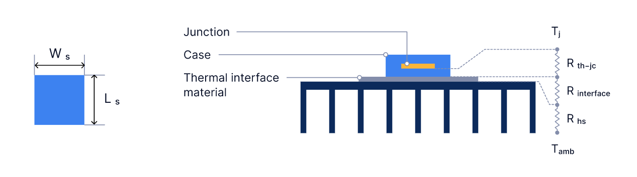
Example
Minimal amount of boundary information
The baseline calculation determines the total resistance to heat flow from the junction of the heat-generating component, through the case and heat sink, to the surrounding environment. It requires three primary parameters:
| Input symbol | Explanation | Units |
|---|---|---|
| This is the ambient temperature | Kelvin | |
| This is the maximum junction temperature | Kelvin | |
| This represents the heat dissipated from the heat source | Watts |
The resistance to heat flow from the junction of the heat-generating component, through the case and the heat sink to the environment, will be automatically calculated using the following equation:
Thermal interface material refinement
| Input symbol | Explanation | Units |
|---|---|---|
| This is the thickness of the thermal interface material | Meters | |
| This is the thermal conductivity of the thermal interface material | ||
| This is the width of the heat source | Meters | |
| This is the length of the heat source | Meters |
The resistance to heat flow from the junction of the heat-generating component, through the case and the heat sink to the environment, will be automatically calculated using the following equation:
Junction information refinement
| Input symbol | Explanation | Units |
|---|---|---|
| This is the thermal resistance between the junction and the case |
The resistance to heat flow from the junction of the heat-generating component, through the case and the heat sink to the environment, will be automatically calculated using the following equation:
Updated about 1 month ago