
Case type
Introduction
ColdStream supports 4 types of cases. The type of case dictates what ColdStream needs to do. Here you find a summary of all supported case types:
- Base case
- Simulation
- Custom Design
- Standard Design
As highlighted in this article, to successfully design a heatsink, we strongly advise to follow a workflow. A workflow is a combination of cases. A workflow always starts with a base case. This type of case cannot run but contains the initial setup, geometry and input, which will be transferred to the other type of cases upon creation.
ColdStream supports CFD simulations. These correspond to the cases of type Simulation. Simulations are ideal early on in the workflow for setup guidance or to validate designs towards the end of the workflow.
ColdStream offers two different forms of generative design, where it will generate designs based on user-specified targets. The difference between Standard Design and Custom Design will become clear in their dedicated sections.
ImportantColdStream only considers steady state behavior. It is not possible to submit time-dependent problems.
Base case
The base case serves as the foundation for the rest of the workflow. This case contains the initial geometry and input parameters upon which all subsequent cases will be built. It represents an initial configuration or scenario. This setup can be modified in the different cases, should it be required. It is recommended to follow the Base case setup with a simulation, for engineers to validate and/or analyze the performance of their case.
Simulation
Introduction
This chapter describes the modeling approach used within ColdStream to perform CFD simulations. The equations used to model the fluid and solid regions' physical behavior are explained. The different turbulence models, used to describe the turbulent behavior of fluids, available in ColdStream are also described.
Fluid region
Navier-Stokes equations
In ColdStream, the physical behavior of fluids is modeled using the Navier-Stokes equations, conservation of mass and momentum, in combination with the energy equation. [1], [2]
For incompressible fluids, the continuity equation can be written as:
Where represents the density field, is the velocity field and is the time.
The incompressible flow assumption holds well for all fluids at low Mach numbers (up to approximately 0.3). For higher Mach numbers, the compressibility effects cannot be ignored and should be taken into account. The Mach number for gas flows can be calculated using the following equation (liquids are always assumed to be incompressible):
Where is the velocity magnitude, represents the speed of sound, is the heat capacity ratio, is the specific gas constant and is the temperature.
The conservation of momentum can be written as:
Where is the velocity field, is the density, is the dynamic viscosity, is the pressure and an optional body force (for example gravity).
The energy equation, as a function of enthalpy, can be written as:
Where is the thermal diffusivity and is an energy source (for example an internal heat source due to an exothermic reaction).
The thermal diffusivity is defined as:
Where represents the thermal conductivity and the specific heat capacity.
The following equation relates the enthalpy to the temperature for incompressible fluids:
The energy equation can therefore be easily written in terms of the temperature:
Body forces
For forced convection applications:
For natural convection applications, the body Boussinesq approximation is applied to model the buoyant behavior of the fluid. Therefore, the body force is taken as:
Where is the gravitational acceleration, the coeficient of expansion. Note that is taken as a function of the reference temperature and therefore is constant during the simulation.
Turbulence model
Different modeling approaches exist to predict the effects of turbulence on a flowing fluid. An overview of the available turbulence models within ColdStream and a flow chart to help you select the best model for your specific problem can be found here.
Solid region
For the solid region, only the energy equation needs to be solved:
Where is the density of the solid material, is the enthalpy, represents the thermal diffusivity and is a heat source (for example due to Joule heating).
Similarly to the fluid equations, the solid energy equation can also be written in terms of the temperature:
Where is the specific heat capacity and represents the thermal conductivity of the solid material.
ColdStream allows the use of either isotropic or anisotropic properties, depending on the material thermophysical properties.
Interface modeling
The heat exchange between different components, for example, a solid and a fluid, depends only on the temperature difference between the respective cells adjacent to the wall. At this wall, interface equilibrium conditions are imposed, requiring that the heat flux over the interface is equal and from the fluid side only dependent on the effective thermal conductivity, which accounts for the thermal conductivity of the fluid and the turbulent diffusivity:
Furthermore, the temperature on each side of the interface between a fluid and a solid should match:
While computationally expensive, this approach provides a detailed insight into the physics of the problem, which in turn, will provide the optimizer with a more realistic performance of each design. This is fundamental to correctly exploring the design space and eventually finding a truly optimal design.
References
- https://www.eng.auburn.edu/~tplacek/courses/fluidsreview-1.pdf
- https://www.grc.nasa.gov/www/k-12/airplane/nseqs.html
Standard Design
Introduction
The Standard Design mode utilizes a parametric approach, driven by user input, to efficiently generate conventional, highly-optimized heatsink designs. Typical examples include fin heatsinks for LEDs, extruded heatsinks for PCBs, and standard processor heatsinks.
A heatsink transfers heat from a component to a fluid medium where the heat is dissipated away. The general principle is that an increased surface area yields better thermal performance.
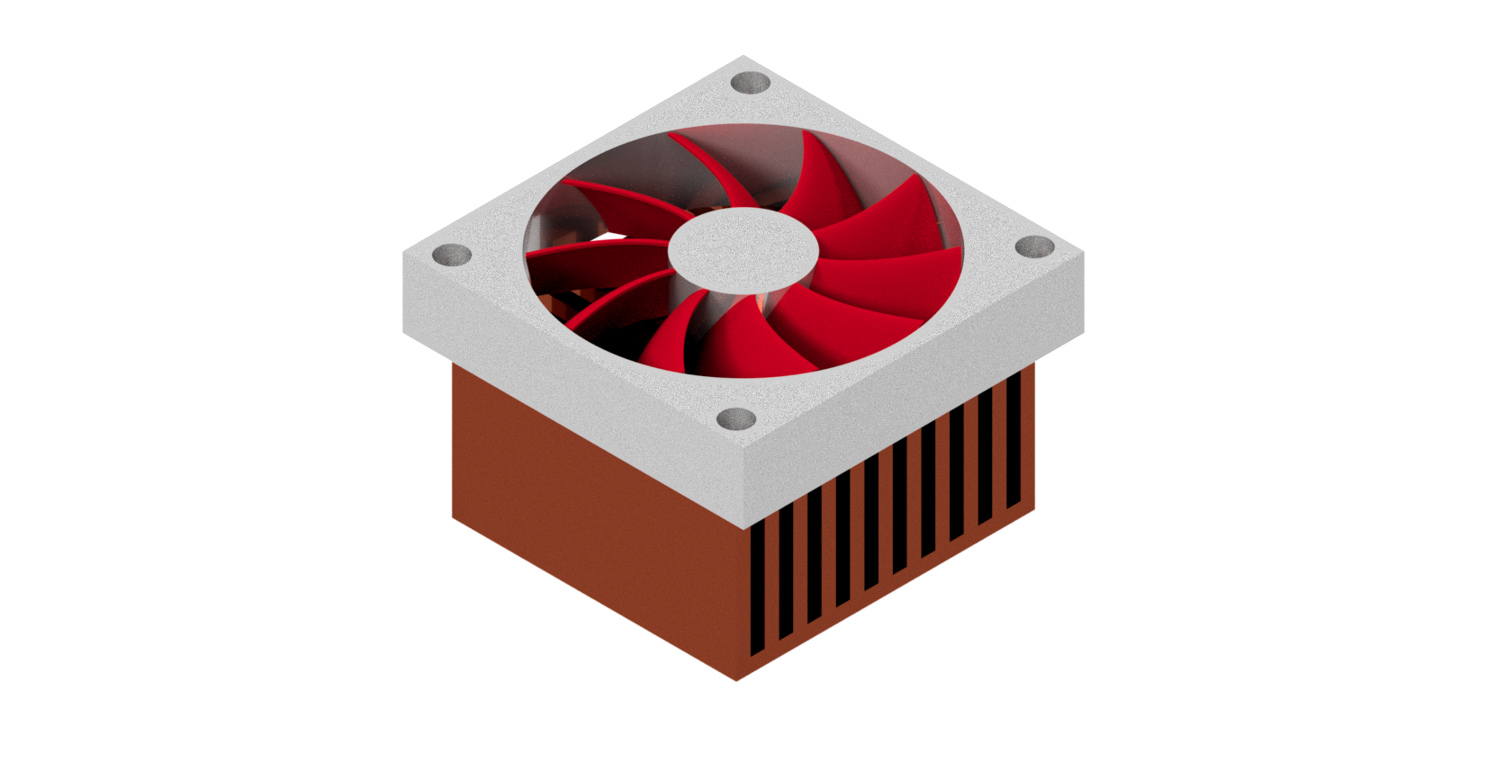
Fin processor heatsink.
NoteStandard Design cases generate optimized, easily manufacturable heatsinks based on standard industry profiles.
Design Templates & Manufacturing Options
As a ColdStream user, you have full control over what shapes ColdStream needs to consider as well as the manufacturing settings to make those structures. The type of structures that will be generated are grouped by manufacturing, where a distinction is made between: CNC, 3D Printing, Die casting, Sheet Metal, Roll bonding and Skiving.
CNC
CNC milling is a highly versatile manufacturing technique that allows for the creation of various heatsink geometries by precisely removing material from a solid block. The parametric templates available for this technique include:
- Discontinuous Structures (Circle, Rectangle, Diamond, Ellipse): These discrete, pillar-like elements extrude from a base plate. They offer a large surface-area-to-volume ratio and perform well regardless of orientation. Because the surface is discontinuous, the thermal boundary layer is constantly broken along the direction of airflow, which increases heat transfer. However, this discontinuous geometry also increases the pressure drop across the heatsink, resulting in a lower flow rate for a given pressure condition.
- Continuous Structures (Continuous Rectangle, Serpentine): These designs feature continuous walls or channels, such as traditional straight fins (Continuous Rectangle) or winding paths (Serpentine). Because the geometry is continuous along the primary direction of flow, a thermal boundary layer will build up along the entire surface.
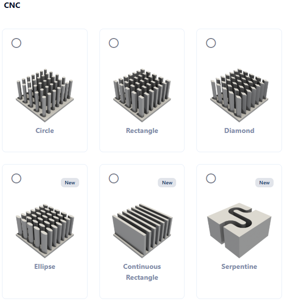
Example of CNC templates.
NoteResearch generally shows that continuous fin heatsinks perform better in natural convection scenarios. Discontinuous structures are advantageous when fluid flow comes from multiple directions (as their performance is orientation-independent) and they often outperform continuous fins in forced convection cases, even when accounting for the increased pressure drop.
3D Printing: TPMS structures
ColdStream supports the optimization of heatsinks using Triply Periodic Minimal Surfaces (TPMS) structures, which are compatible with additive manufacturing techniques such as SLS, SLM, and LPBF. The available TPMS structures include, between others, Gyroids, Schwarz, Diamond, Lidinoid, Split P, Neovius, GP Prime Two, S Surfaces, Fischer Koch and IWP.
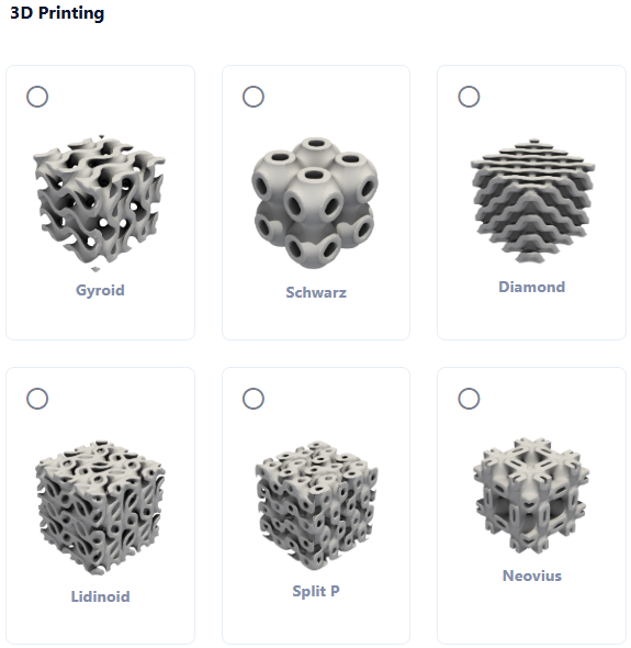
Example of 3D Printing templates.
Die Casting
Die casting is a highly efficient manufacturing process ideal for the high-volume production of metal parts. It involves forcing molten metal under high pressure into a reusable mold cavity. A defining characteristic of die-cast heatsinks is the mandatory inclusion of draft angles (tapered profiles) on all cooling structures to allow the finished part to be successfully ejected from the mold.
While these structures share the same underlying thermal and fluid dynamics as their CNC-machined counterparts, they are parametrically generated to adhere to these strict casting constraints. The templates available for this technique include:
- Discontinuous Structures (Circle, Rectangle, Ellipse): These discrete, tapered pin elements provide the same high heat transfer, boundary-layer disruption, and orientation independence as machined pins, but are structurally optimized for mold release.
- Continuous Structures (Continuous Rectangle, Serpentine): These designs feature continuous, drafted walls or channels. Thermally, they perform exactly like extruded or machined fins but utilize tapered profiles for manufacturability.
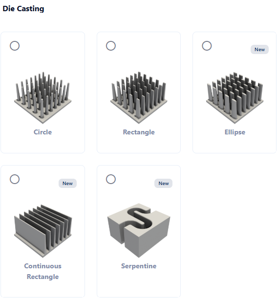
Example of Die Casting templates.
Sheet Metal
Sheet metal forming is a cost-effective manufacturing process for large production volumes that results in exceptionally lightweight designs. This makes it highly attractive in the automotive industry, particularly for battery cold plates. The parametric templates available for this technique include circular and rectangular dimples.
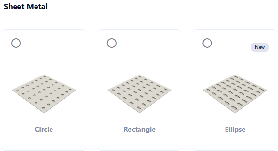
Example of Sheet Metal templates.
Case setup
Setting up a Standard Design case is very similar to a regular CFD simulation, with two key differences:
- The Design Region: Instead of importing a CAD file that already features cooling structures, an empty design region must be defined. This requires creating a dedicated body in the CAD software. The volume of this new body establishes exactly where ColdStream is allowed to generate the parametric heatsink.
- Targets: Optimization targets must be defined to establish which performance metrics ColdStream should prioritize.
Design Region Rules
- The design region must be oriented along the Cartesian axes.
- While it can take arbitrary shapes, a flat base is highly advised.
- The parent region of the design must be a fluid type, and at least one of the flat faces of the design region must touch a solid region.
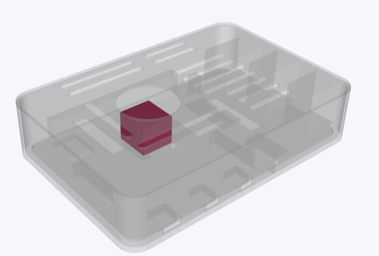
Design subregion inside of the fluid region.
Optimization Best Practices
Multiple shapes, manufacturing settings, targets or materials can be selected within a single Standard Design case. ColdStream will return the best heatsinks for each configuration, enabling the selection of the most suitable option.
ImportantDiabatix highly advises limiting the number of design variables per case as much as possible. It is more efficient to split highly diverse options into multiple cases (e.g., evaluate CNC machined Ellipses in Case A, and 3D printed Gyroids in Case B).
Results
Once submitted, the optimizer iterates through the pre-defined parameters (such as element dimensions, base plate thickness, and the number of elements) to find the optimal configuration. The results page provides a detailed evolution of this optimization process. For each iteration, the geometry, thermal/fluid performance, and multiple contour fields are available on the platform. The design evolution is plotted with the design iteration on the x-axis and performance on the y-axis. The specific geometric parameters of the heatsink for any iteration can be seamlessly accessed and evaluated.
NoteThe correlation-based Standard Design mode provides quick insights into the optimal configuration for a specific application using minimal resources.
Custom design
Introduction
Custom Design utilizes a fully generative approach, providing complete flexibility to create highly optimized, free-form heatsink geometries. Unlike Standard Design, the solver is not restricted to predefined parametric templates. The generated structures can be guided and constrained by specifying a desired manufacturing technique and its governing settings.
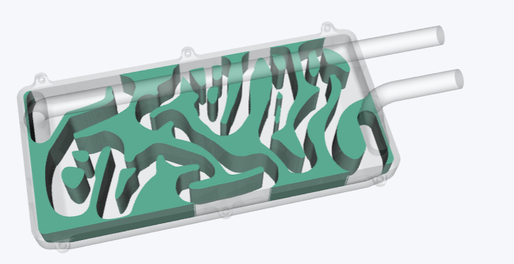
Example of a generative design solution.
NoteFor detailed information regarding the available manufacturing techniques and their specific parameters, please refer to the dedicated manufacturing documentation.
Case setup
The setup for a Custom Design case closely mirrors that of a Standard Design case. An empty design region must be defined in the CAD geometry to establish the allowable volume where the generative solver can create structures.
However, Custom Design introduces the following key differences:
- The design region does not need to be aligned with the Cartesian axes.
- The parent region is not restricted to a fluid type; it can be either a solid or a fluid.
- The design region is not required to be in contact with another solid body, although it is recommended.
- A base plate is not automatically generated by the solver.
Initialization
The outcome of a Custom Design optimization can be guided by initializing the design region with an existing geometry, either from a previous simulation or a custom CAD model. To utilize initialization, the following steps must be taken:
- Enable Initialization: Turn on the initialization slider for the relevant design domain.
- Upload Geometry: Upload a STEP or STL file of the initial design. Note that only the portions of the uploaded geometry that overlap with the defined design region will be taken into account.
- Select Mode: Select the desired initialization mode. Three modes are supported:
- Only Add: The initial design geometry remains strictly intact; the solver is only permitted to add material to the surrounding void space.
- Only Remove: The existing void spaces (e.g., fluid channels) of the initial design remain strictly intact; the solver is only permitted to remove material from the initial solid structure.
- Add and Remove: The initial design serves purely as a structural starting point. The solver has complete freedom to both add structures to and remove material from the initialized geometry.
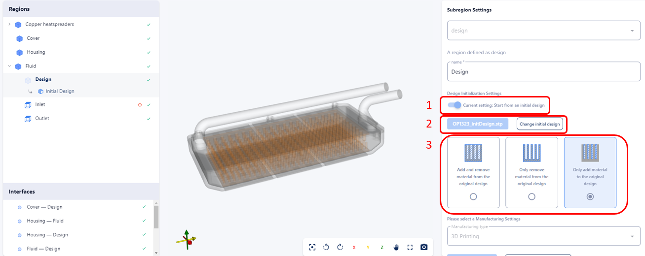
How the different initializations are selected.
ImportantFor 2D manufacturing methods, the initializer design must also be strictly 2D. Consequently, including a base plate in the initial geometry is not recommended, as it skews the application of manufacturability constraints.
ImportantThe Only Add mode is incompatible with Sheet Metal manufacturing constraints. Combining this mode with an initializer that already consists of a sheet metal plate will result in unmanufacturable designs.
Results
The results page provides a detailed evolution of the optimization process across several extracted data points. For each evaluated data point, the resulting geometry, performance metrics, and multiple field contours are available on the platform. The design evolution is graphically plotted with the design iteration on the x-axis and the corresponding performance on the y-axis. The specific geometry and thermal/fluid results for any particular iteration can be seamlessly accessed and evaluated.
Updated 9 days ago