
Interfaces
Introduction
Once your CAD geometry is successfully uploaded and populated, ColdStream automatically detects all interfaces between adjacent regions. An interface represents the exact physical contact area where thermal and fluid interactions occur between two touching bodies.
ImportantIf an expected interface is missing from the auto-detected list, it means the two regions are not perfectly mating in the 3D model. This implies an unintended gap or geometric interference exists between them. To resolve this, you must fix the alignment in your original CAD software and re-upload the geometry.
Managing Interfaces
ColdStream automatically lists all valid, detected interfaces in the case setup menu. If an interface is accidentally deleted from this list during the configuration process, it can easily be reinstated. Simply click the + (plus) button within the interfaces section to select and restore the connection.

Creation of interfaces.
Thermal Interface Materials (TIM)
By default, ColdStream assumes perfect thermal contact at any detected interface. However, to accurately model real-world thermal contact resistance, you can explicitly assign a Thermal Interface Material (TIM) to these boundaries.
When applying a TIM, keep the following rules in mind:
- Between Regions: TIMs can be freely applied between standard regions (e.g., between two solid bodies).
- Solid-to-Fluid: A TIM can be assigned at the interface between a solid and a fluid region. This should be done strictly at the user's discretion, provided it makes physical and thermodynamic sense for the specific engineering application (e.g., simulating a thin coating or fouling layer).
- Design Regions: A TIM cannot be applied at the interface between a general subregion and a design region.
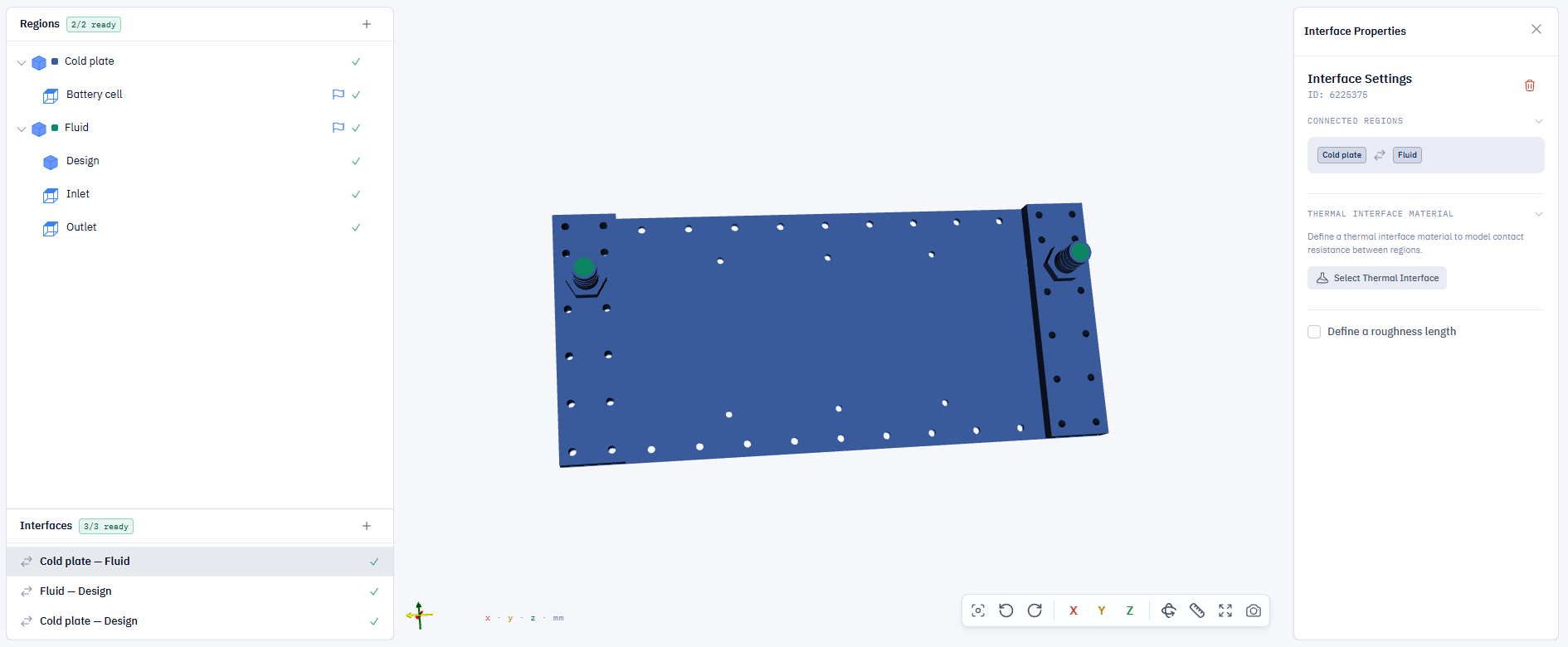
Thermal interface material configuration
Updated 18 days ago